This toolbox provides graphical tools to create maps of the environment from sensor data, as well as tools to edit and load these maps.
The mapping process
The mapping process comes down to gathering sensor measurements of the environment's structure while driving around with the robot. This sensor data, combined with the corresponding measurement positions, yields a set of discrete obstacle positions in global coordinates, which can easily be converted to the occupancy grid map representation used.
However, the robot's odometry is inherently erroneous, so that we cannot rely on the measurement positions returned by the odometry. There are two ways implemented to solve this problem:
- Reference points: Tell the robot its actual position from time to time, so that the odometry drift can be corrected internally. Points like these are called reference points, because they provide a reference with which the robot can correct its odometry. The larger the environment to be mapped, the more reference points are required.
- SLAM: By using a Simultaneous Localization and Mapping algorithm, there is no need to define reference points in the environment. To use this mode, the toolbox GMapping must be installed.
For further information, please read the page Introduction to the mapping process.
Prerequisites for mapping
Before you can start to create maps, you'll have to make certain that you meet some prerequisites. The mapping tool Simple Mapper needs to be started in an instance of miracenter that is running a sufficient configuration for mapping.
What does this mean, exactly?
It means that the following data needs to be present when starting the mapping:
-
Odometry data: A channel containing continuous data of the type
mira::robot::Odometry<2>. -
Range scan data: A channel with containing continuous data of the type
mira::robot::RangeScan. - Transformation tree: A transformation tree that specifies and connects the frame of the range finder with the robot's odometry.
Where do I get such a configuration?
Please have a look at the SCITOSConfigs package. It provides a configuration file SCITOS-mapping.xml that loads the required SCITOS- and range finder drivers for your robot.
Simple Mapper tool
The tool Simple Mapper provides an easy to use interface to create occupancy grid maps from laser range finder measurements and rectified odometry data. Simply load the tool in an appropriate instance of miracenter (see Prerequisites for mapping) by pressing CTRL+D and selecting Simple Mapper.
You should see a window like the one below:
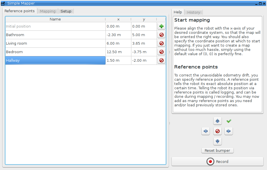
The typical mapping process is as follows:
Using reference points:
- Determine a sufficient number of reference points of the environment (see The mapping process).
- Start the Simple Mapper tool and enter the determined reference points.
- Initiate mapping by starting the recording of the sensor data.
- Map your environment by driving from reference point to reference point, stopping and logging them every time you reach them.
- Stop recording and let the Simple Mapper build the map.
- Save the created map (see Map files).
Using SLAM:
- Start the Simple Mapper tool.
- Initiate mapping by starting the recording of the sensor data.
- Map your environment by driving around so that the whole environment is covered. While driving close loops and visit intersections multiple times to reduce ambiguities.
- Stop recording and let the Simple Mapper build the map.
- Save the created map (see Map files).
For further information, please read the page Simple Mapper.
Simple Map Editor tool
The tool Simple Map Editor provides an easy to use interface to edit maps created with the Simple Mapper tool. Simply load the tool in any instance of miracenter (the Prerequisites for mapping do not apply here) by pressing CTRL+D and selecting Simple Map Editor.
You should see a window like the one below:
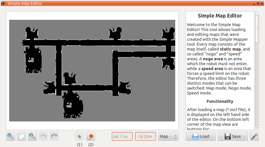
The typical map editing process is as follows:
- Load the MCF file of a previously created map (see Map files and Simple Mapper tool).
- Use the pencil tool to correct mapping mistakes like range sensor noise and such.
- Create nogo, speed areas, one way areas and forbidden areas appropriate for the mapped environment.
- Save the map to update the map's MCF and PNG files.
- Either reload MIRA with the edited maps or directly publish the edited maps to the appropriate channels.
For further information, please read the page Simple Map Editor.
Map files
Both Simple Mapper and Simple Map Editor use a file format called MCF, as in map configuration file. When saving the built map with Simple Mapper, seven files are created: The MCF file itself as well as PNG and XML files for the static, nogo and speed map. A folder containing a valid mapping structure should look similar to this:
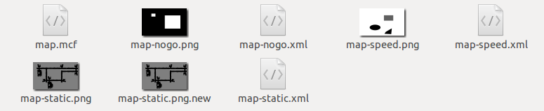
The MCF file stores the path to the static, nogo and speed map XML files, as well as the descriptive primitives of the nogo and speed areas. The PNG files store the actual map information, while the corresponding XML files describe the map information contained in the PNG files.
For further information, please read the page Map Configuration Files (MCF).