This page provides some information about the mapping process in general, and the concepts used in this toolbox.
General mapping process
In a nutshell, the mapping process consists of driving the robot around the environment to be mapped while collecting sensor measurements of the environment's structure, or rather obstacles. This sensor data, combined with the measurement positions, yields a set of obstacle positions in global coordinates, which converts easily into any map representation. However, there is a practical problem to this process:
The robot's position and orientation (henceforth called "pose") accumulates small errors along the way.
This is because the robot's odometry is susceptible to systematic and non-systematic errors. Due to the nature of differential drives, most translational errors result from falsely perceived rotations due to uneven floors or wheel slippage. For small areas, this problem is negligible. When mapping a room, for example, the range of the robot's laser range finder most likely covers most of the room with a single measurement. To get the "full picture" of the room's structure, the robot needs not drive very far, so the pose error stays quite small. Small enough, in fact, that the map will be of good quality without any noticeable distortions due to odometry errors.

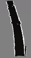
For larger environments, these errors become a problem. The uncertainty of the robot's pose grows proportional to the distance the robot has driven. Imagine mapping a long corridor of 50m length, during which the robot accumulates a constant drift to the left. At the end of the corridor, the pose reads (x,y)=(49.2m, 1.7m) instead of the actual position (50m, 0m). Instead of a straight map of the corridor, we get a sort of "banana" shaped map as seen in the picture below.
How to counter this problem? There are two ways to solve this issue:
- Using Reference points: Tell the robot its actual position from time to time, so that it can correct the accumulated pose error and continue mapping a distortion-free map.
- Using SLAM: By using a Simultaneous Localization and Mapping algorithm, there is no need to define reference points in the environment. Geometries seen by the robot's sensors will be analysed and stored in association with the estimated positions of the sensor readings. An intelligent algorithm then tries to find structural similarities between the current and past sensor readings. Such similarities can serve as indicators that the robot saw the same environmental feature in all sensor readings. By analysing the way the feature was perceived each time, the relative observation positions of the various sensor readings can be inferred to a certain degree. This will allow the algorithm to bound the accumulated odometry error. Using this algorithm is much easier, but it will take more computation time and it requires careful planning of the driven path while mapping. Previously visited locations have to be re-visited regularily, e.g. the driven path should exhibit several self-intersections / loops (therefore this procedure is also known as loop closing). In unstructured environments with no obstacles or completely uniform obstacles, the algorithm might fail to calculate the relative positions of observed features, hence introducing distortion into the map.
Coordinate systems
To be able to do that, we need to have a coordinate system for our environment - otherwise, it would be impossible to specify the actual current position of the robot. Some factory halls and other industrial buildings already have a fixed coordinate system, which can be read from the floorplans. In most cases, however, the environment (i.e. an apartment) has no fixed coordinate system - it needs to be determined.
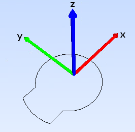
Let's examine the robot's own coordinate frame. The image below shows the orientation of the coordinate axes against the contour of a SCITOS A5 robot. Axis x is equivalent to the forward driving direction of the robot.
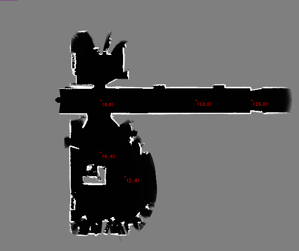
Using this coordinate system orientation, we can define a coordinate system for the environment being mapped by specifying a certain point as the origin (0m,0m). This enables us to measure the coordinates of distinct points in the environment, which we shall call "reference points". The picture below shows a map of dimensions approximately 20m times 20m, with some example reference points added.
While mapping, those points are used to tell the robot its actual current position, so the accumulated pose error is reset to zero. This means that we do not need to tell the robot where it is all the time - only at sensible intervals.
A good rule of thumb is that every 10 to 20 meters, the robot should be told its actual position.
Reference points
We call those positions "reference points", because they provide a reference position with which the robot can correct its accumulated pose error. Depending on the dimensions of the environment being mapped, we need to determine a number of reference points.
Some guidelines for determining reference points in your environment:
- Use distinctive points in the environment like intersections, door steps, middles or ends of corridors, etc.
- Use points for which the coordinates can be determined easily - e.g. don't use the door at approximate coordinates (12.3m, 1.2m), rather use the intersection of corridors at (15m, 0m).
- Try to align your points - if every new point is on a horizontal or vertical straight line from a previous point, determining the coordinates becomes a lot easier.
- Use points that are on the most convenient path to drive - don't make the robot maneuveur into a tight corner just to reach a reference point.
- Consider the way the pose error accumulates - slowly for driving relatively straight, and fast for rotations. Therefore, a reference point every 10m-20m is enough in a corridor, but when driving around a sharp corner, consider placing a reference point before and after the corner. Also note that odometry error might accumulate faster or slower for different robots, and can significantly depend on the floor surface.
These guidelines should give you some idea on how to determine good reference points. Using these points, you can now create a map using the tool Simple Mapper.