| Previous: Authorities | Next: Concepts |
|---|
Contents
- Overview
- The Transformer
- Transforms and Channels
- Specifying Transforms in the Configuration File
- Specifying Transforms from C++
- Publishing Transforms Indirectly
- API Reference
- Requirements and Implementation Details
Overview
On a robotic system, usually many different coordinate frames play a major role, e.g. the pose of the robot within the world, the position of the laser range finder on the robot, the position and orientation of a camera, etc. The transform framework manages all those different coordinate frames and their relation to each other. Similar to a scene graph, the coordinate frames are stored in a tree-like structure, i.e. each coordinate frame stores its transformation in relation to its parent node. In fact, the transformation is expressed as a relative pose consisting of a position and an orientation. This kind of transformations is also known as rigid transform or isometry. In order to preserve handedness, reflections are not allowed as part of such transformations. The framework eventually allows to compute transformations between any two coordinate frames indirectly related within the transform tree.
Note that not all transformations handled by the transform framework need to form a single tree. Instead, disjoint transform trees that form a forest are also possible.
The Transformer
The central class of the transformation framework is the Transformer (mira::Transformer). The Transformer holds a number of nodes (mira::TransformerNode). Each node acts as a container to hold a transform, e.g. a two-dimensional rigid transform (mira::RigidTransform2f). Furthermore, the transformer holds a number of directed links between pairs of nodes, where in each pair, one node acts as parent and the other node acts as child. Using the links, a transformer can concatenate a number of transforms, say A, B, and C (in that order), to obtain a resulting transform D(x) = C(B(A(x))).
Set up a transformer
The following code snippet shows how to set up a transformer with a number of linked nodes.
First, we set up a transformer 't' to hold all our transforms.
Then, we add a new node named 'root' and set its transform to the identity transform. Let's ignore the timestamp (Time::now()) for now.
We add some more transforms, namely 'a', 'b', and 'c', and define their parent-child relations by adding links between them. Each transform of a node is interpreted as relative to the node's parent's pose (= cumulated transformation).
So far, we set up a number of transforms and defined their relations to look like this: root->a->b->c. This way, we can build complex directed trees of transformation nodes.
Query the transformer
To find out the transformation (relative pose) between any two of the nodes, we can query the transformer for the desired transform.
This only works if there are links defined between the specified nodes. Each link transformation can be queried in the parent to child direction, or also in the opposite direction, which will just return the inverse transformation.
This kind of query hides all the nodes in the transformer between 'c' and 'root' and only returns the resulting concatenated transformation (inverting individual link transforms if necessary).
We can, however, also query the transformer for the full chain of transforms between 'c' and 'r'.
The chain (mira::TransformerBase::Chain) then contains all transforms that have to be applied to get from 'c' to 'r'. If a link transform had to be applied inversely, then the chain contains the inverse of that transform, ensuring that all transforms in the chain have to be applied forward to get from 'c' to 'r'. The chain contains two getters, 'forward' and 'inverse', to get the forward and the inverse list of nodes ('c' to 'r' / 'r' to 'c').
Interpolation
So far, we have ignored the timestamp that has to be provided when setting the transform of a node. A node can not only contain one transform, but a sequence of transforms, each with a different time stamp. For an example, consider the pose of a mobile robot. At different times, the robot will have different poses (expressed as transformations between the robot's internal coordinate frame and the world frame). To describe that situation, we would have a node and set a new transform each time the robot changes its pose. The transformation allows temporal interpolation of transforms of a node. The following code illustrates the usage. Let's give the node 'a' two different transforms with two different time stamps, now and one second in the future.
We can now query the transformer for a transform between the two specified time points, let's say one millisecond from now. By not specifying a filter argument, we will apply a NearestNeighbourInterpolator, i.e. we are querying the transformation set with the timestamp closest to our query time.
We can, however, also interpolate or extrapolate from the given discrete sequence of transforms, by using a proper interpolator:
Transformation types
Transform nodes are not restricted to mira::RigidTransform2f. Each node can describe a rigid transformation either in 2D or 3D, and can optionally include a covariance matrix over its transformation (thus describing state + uncertainty). Nodes of arbitrary transformation types can be combined within a tree.
Transformations can be converted between these types using mira::transform_cast().
Conversions follow these rules:
- Casting from 3D to 2D selects the x/y/yaw subpose.
- Casting from 2D to 3D sets z/pitch/roll to 0.
- Casting to a transform without covariance just ignores a present covariance matrix.
- Casting from a transform without covariance to a transform with covariance (or from 2D with covariance to 3D with covariance) initializes all (missing) covariance values to 0.
Based on this conversion mechanism, arbitrary transformation types can be queried from a transformer, it will automatically convert all involved transforms to the required type.
Transforms and Channels
As described above, each transformation is a node within a transform tree and the transforms are specified relative to the parent transform. The transformation value itself is stored in a channel with the same name (including the namespace etc.) as the transform node. Hence, each transform node has its associated channel that contains the actual RigidTransform or Pose respectively.
The channels, containing the transformation data as well as the transformation topology, are shared among different connected MIRA frameworks. This allows the transformation trees to be distributed across multiple frameworks.
Channels also provide the functionality to store value sequences as described above in subsection Interpolation, by using multiple slots on the channel.
Static and dynamic transforms
By default, transformations can be updated at any time, the slot mechanism of the associated channel will make sure to keep as many historical values as required by channel/transform subscribers to query past poses. In some cases, however, it is clear that a transformation is fixed, and updating it does not mean there is a new point in a sequence of positions changing over time, but just new knowledge about the fixed position. Consider e.g. the position of a moving robot in space (moving transformation) vs. the position of an attached camera w.r.t. to the robot body (fixed transformation). When (re-)calibrating the camera, the belief of its position may change, but it means the camera has always been at the updated position, not moved from old to new position. Not respecting the fixed nature of this transformation may result in accidentally interpolating/extrapolating it, in particular when it is part of a queried transformation chain where other link values SHOULD be interpolated.
A simple way to prevent accidental interpolation is to only ever store one value on the associated channel, and overwrite it on update (instead of adding another slot).
In order to distinguish this, transform nodes can be set to FIXED or MOVING type (e.g. when adding them with FrameworkTransformer::addLink()). For fixed links, their channel slot limit will be set to 1.
Specifying Transforms in the Configuration File
The topology of the transformation tree can be specified within the configuration file using the <link> tag. With each <link> tag, a link between a parent and child frame can be created. The following example creates two links between the WorldFrame, the OdometryFrame, and the RobotFrame:
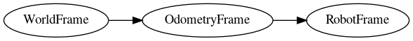
Beside the sole topology, the <link> tag also allows to specify transforms, e.g. the position of the laser range finder on the robot:
The transform tree will now have the following topology:

The transforms can be specified as 2D transforms as above, or as 3D transforms (see <link> for an example).
By specifying such a transform, you can set the initial value of a transformation. The transform may later be changed by a running publisher.
Specifying Transforms from C++
Transform links can also be created in code.
Typically, the transformations of a complex system like an entire robot application are specified using a combination of code and configuration. For a certain part, like a camera or even a more complex device like a non-rigid arm, the respective 'driver' unit will define and link all the involved transform frames in its implementation, and also make sure to publish (update) it it if required, e.g. when moving the arm. An application designer can then compose an application from different software packages, typically by creating a configuration file that is used to instantiate all the required modules. A part of the application configuration (or, as part of that, the robot device specification) will be the description of e.g. how the arm and the camera are attached to the robot.
Publishing Transforms Indirectly
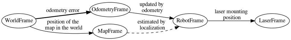
Instead of setting the value of a certain transformation link directly, it is also possible to specify a transformation between a node A and its child B such that a certain relation between different but connected frames C and D is achieved. The FrameworkTransformer provides this functionality and will internally query all the related transformations between C/D and A/B, then determine and publish the required value for the transformation between A and B.
Here is a practical example: The robot's position is tracked by a combination of odometry (measuring robot motion) and map alignment for global correction. In order to allow independent updates, odometry and correction pose are represented as separate nodes. The odometry publisher frequently updates the RobotFrame with its measurement. The correction algorithm observes the relative pose of the robot to the map, but it only updates the OdometryFrame (= the correction transformation). Instead of querying the RobotFrame and calculating the correction, it can just specify the pose of the robot on the map to the FrameTransformer and ask it to adapt the OdometryFrame accordingly.
| Next: Concepts |
|---|